An Introduction to Low-Pressure GC-MS (LPGC-MS)
Leverage Your MS Vacuum to Significantly Speed Up Analyses

- Up to 3.3x faster than conventional GC-MS.
- Saves money by reducing helium use up to 81%.
- Factory-coupled, leak-free kits make setup as simple as a column change.
- Ideal for fast GC-MS and GC-MS/MS methods.
Using a mass spectrometer as a GC detection system has many advantages when it comes to compound identification and quantification, but GC-MS users have another untapped opportunity: speeding up analyses by using the MS vacuum to lower pressure within the column. The amount of the GC column that is affected depends on the column dimensions, with traditional column formats limiting the vacuum’s effect to the last few meters of the column. However, when you lower the pressure throughout the whole column you can really speed things up!
Low-pressure GC-MS (LPGC-MS) is a technique that uses the MS vacuum system, along with a specially designed column setup, to lower pressure inside the entire column, thereby significantly speeding up analysis. In addition to the speed benefit, LPGC-MS can also provide a cost savings by dramatically reducing helium consumption. By using a short, 0.53 or 0.32 mm analytical column that is inserted directly into the MS and a flow restrictor on the GC inlet side, low pressure can be maintained throughout the analytical column. Using LPGC-MS, some efficiency is traded for speed, but because a mass spectrometer is used, most coeluting components can be deconvoluted by the MS.
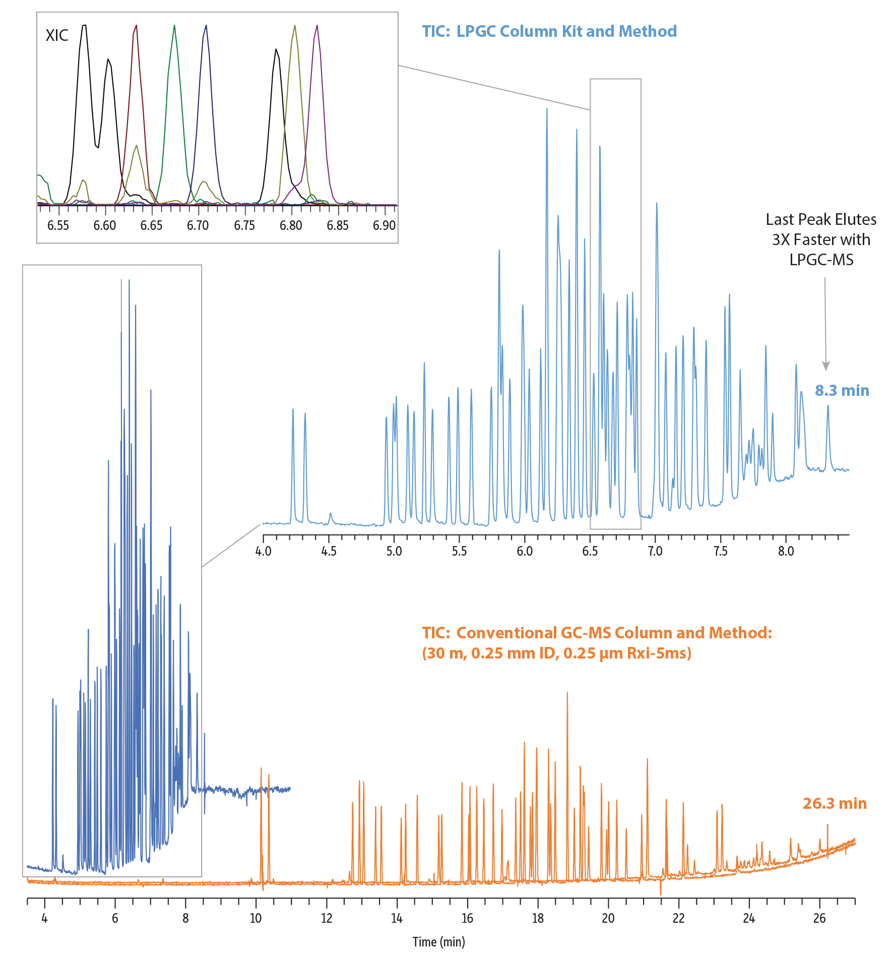
Figure 1 and Table I demonstrate the performance gains that can be achieved by lowering the pressure in the GC column compared to using a conventional GC-MS setup. This technique, not surprisingly, is known as “vacuum-outlet GC,” or more commonly as “low-pressure GC-MS” or LPGC-MS. This article will explore how to utilize LPGC-MS and specially designed, pre-connected LPGC column kits to speed up gas chromatographic analyses.
Figure 1: This LPGC-MS analysis of pesticides in food is 3.1x faster and uses 54% less helium than a conventional setup even though a lower efficiency column is used. Because of the increased linear velocity, peak widths are narrower, creating taller peaks and potentially providing greater sensitivity. In addition, even densely populated peaks can still usually be resolved spectrally.
| Peaks | Conc. (...) | tR (30 m) | tR (LPGC) | |
|---|---|---|---|---|
| 1. | Chloroneb | 0.4 | 10.337 | 4.225 |
| 2. | Pentachlorobenzene | 0.4 | 10.562 | 4.320 |
| 3. | α-BHC | 0.4 | 12.956 | 4.939 |
| 4. | Hexachlorobenzene | 0.4 | 13.154 | 4.997 |
| 5. | Pentachloroanisole | 0.4 | 13.273 | 5.017 |
| 6. | β-BHC | 0.4 | 13.610 | 5.106 |
| 7. | δ-BHC | 0.4 | 13.773 | 5.154 |
| 8. | γ-BHC | 0.4 | 14.341 | 5.293 |
| 9. | Tefluthrin | 0.4 | 14.466 | 5.232 |
| 10. | Endosulfan ether | 0.4 | 14.803 | 5.419 |
| 11. | Transfluthrin | 0.4 | 15.415 | 5.490 |
| 12. | Heptachlor | 0.4 | 15.504 | 5.592 |
| 13. | Pentachlorothioanisole | 0.4 | 16.086 | 5.745 |
| 14. | Anthraquinone | 0.4 | 16.279 | 5.803 |
| 15. | Aldrin | 0.4 | 16.317 | 5.803 |
| 16. | 4,4'-Dichlorobenzophenone | 0.4 | 16.511 | 5.827 |
| 17. | Fenson | 0.4 | 16.708 | 5.885 |
| 18. | Isodrin | 0.4 | 16.987 | 5.980 |
| 19. | Heptachlor epoxide | 0.4 | 17.235 | 6.035 |
| 20. | Bioallethrin | 0.4 | 17.405 | 5.994 |
| 21. | Chlorbenside | 0.4 | 17.626 | 6.123 |
| 22. | trans-Chlordane | 0.4 | 17.766 | 6.167 |
| 23. | 2,4'-DDE | 0.4 | 17.871 | 6.171 |
| 24. | Endosulfan I | 0.4 | 18.052 | 6.249 |
| 25. | cis-Chlordane | 0.4 | 18.109 | 6.256 |
| 26. | trans-Nonachlor | 0.4 | 18.218 | 6.279 |
| 27. | Chlorfenson | 0.4 | 18.232 | 6.226 |
| 28. | 4,4'-DDE | 0.4 | 18.569 | 6.337 |
| 29. | Dieldrin | 0.4 | 18.630 | 6.395 |
| 30. | 2,4'-DDD | 0.4 | 18.756 | 6.395 |
| 31. | Ethylan | 0.4 | 19.106 | 6.460 |
| Peaks | Conc. (...) | tR (30 m) | tR (LPGC) | |
|---|---|---|---|---|
| 32. | Endrin | 0.4 | 19.116 | 6.550 |
| 33. | Endosulfan II | 0.4 | 19.303 | 6.528 |
| 34. | 4,4'-DDD | 0.4 | 19.480 | 6.575 |
| 35. | 2,4'-DDT | 0.4 | 19.562 | 6.603 |
| 36. | cis-Nonachlor | 0.4 | 19.592 | 6.633 |
| 37. | Endrin aldehyde | 0.4 | 19.715 | 6.674 |
| 38. | 4,4'-Methoxychlor olefin | 0.4 | 20.079 | 6.708 |
| 39. | Endosulfan sulfate | 0.4 | 20.225 | 6.803 |
| 40. | 4,4'-DDT | 0.4 | 20.290 | 6.783 |
| 41. | 2,4'-Methoxychlor | 0.4 | 20.521 | 6.827 |
| 42. | Resmethrin | 0.4 | 20.793 | 5.980 |
| 43. | Endrin ketone | 0.4 | 21.235 | 7.082 |
| 44. | Tetramethrin 1 | 0.4 | 21.245 | 6.990 |
| 45. | Tetramethrin 2 | 0.4 | 21.388 | 7.018 |
| 46. | Bifenthrin | 0.4 | 21.402 | 7.011 |
| 47. | Phenothrin 1 | 0.4 | 21.841 | 7.130 |
| 48. | Tetradifon | 0.4 | 21.939 | 7.211 |
| 49. | Phenothrin 2 | 0.4 | 21.956 | 7.157 |
| 50. | Mirex | 0.4 | 22.436 | 7.388 |
| 51. | lambda-Cyhalothrin | 0.4 | 22.545 | 7.293 |
| 52. | Acrinathrin | 0.4 | 22.742 | 7.310 |
| 53. | cis-Permethrin | 0.4 | 23.388 | 7.535 |
| 54. | trans-Permethrin | 0.4 | 23.534 | 7.565 |
| 55. | Cyfluthrins | 0.4 | 24.065-24.310 | 7.698-7.745 |
| 56. | Cypermethrins | 0.4 | 24.436-24.677 | 7.793-7.847 |
| 57. | Flucythrinate 1 | 0.4 | 24.677 | 7.844 |
| 58. | Flucythrinate 2 | 0.4 | 24.898 | 7.899 |
| 59. | Fenvalerate 1 | 0.4 | 25.500 | 8.079 |
| 60. | tau-Fluvalinate 1 | 0.4 | 25.715 | 8.113 |
| 61. | Fenvalerate 2 | 0.4 | 25.732 | 8.140 |
| 62. | tau-Fluvalinate 2 | 0.4 | 25.773 | 8.113 |
| 63. | Deltamethrin | 0.4 | 26.337 | 8.324 |
| Column | See notes |
|---|---|
| Standard/Sample | GC multiresidue pesticide standard #2 (cat.# 32564) |
| GC multiresidue pesticide standard #6 (cat.# 32568) | |
| Diluent: | Acetonitrile |
| Conc.: | 2 µg/mL |
| Injection | |
| Inj. Vol.: | 2 µL split (split ratio 10:1) |
| Liner: | Topaz 4.0 mm ID straight inlet liner w/ wool (cat.# 23444) |
| Inj. Temp.: | 250 °C |
| Carrier Gas | He |
| Detector | TSQ 8000 | |
|---|---|---|
| SIM Program: | 35-550 m/z | |
| Transfer Line Temp.: | 290 °C | |
| Analyzer Type: | Quadrupole | |
| Source Temp.: | 330 °C | |
| Tune Type: | PFTBA | |
| Ionization Mode: | EI | |
| Instrument | Thermo Scientific TSQ 8000 Triple Quadrupole GC-MS | |
| Notes | The reference standard is also available as part of Restek’s 200+ compound GC multiresidue pesticide kit (cat.# 32562). Conventional (30 m) Analysis: Column: Rxi-5ms, 30 m, 0.25 mm ID, 0.25 µm (cat.# 13423) Temp. program: 90 °C (hold 1 min) to 330 °C at 8.5 °C/min (hold 5 min) Flow: 1.4 mL/min LPGC-MS Analysis: Column: LPGC Rtx-5ms column kit, includes 15 m x 0.53 mm ID x 1.00 μm analytical column w/1 m x 0.53 mm ID integrated transfer line and 5 m x 0.18 mm ID Hydroguard restrictor factory connected via SilTite connector (cat.# 11800). Temp. program: 80 °C (hold 1 min) to 320 °C at 35 °C/min (hold 5 min) Flow: 2 mL/min | |
Explore our LPGC-MS applications in the Resource Hub at www.restek.com!
Table I: Compared to conventional GC-MS, LPGC-MS provides significant speed gains and cost savings from reduced helium use.
| Application | Column Kit | Performance Improvement with LPGC-MS | |
| Increase in Analysis Speed |
Reduction in Helium Use |
||
| Alkylfurans | LPGC Rxi-624Sil MS, 10 m (cat. #11804) | 2.3x faster | 72% less |
| Arylamines | LPGC Rxi-35Sil MS, 10 m (cat.# 11806) | 3.3x faster | 81% less |
| MCPDs | LPGC Rxi-17Sil MS, 10 m (cat.# 11805) | 2.0x faster | 69% less |
| Nitrosamines | LPGC Rxi-624Sil MS, 15 m (cat.# 11803) | 1.8x faster | 29% less |
| LPGC Rxi-624Sil MS, 10 m (cat.# 11804) | 2.3x faster | 67% less | |
| Pesticides | LPGC Rtx-5ms, 15 m (cat.# 11800) | 3.1x faster | 54% less |
| Phthalates | LPGC Rxi-35Sil MS, 10 m (cat.# 11806) | 1.4x faster | 67% less |
Why Use LPGC-MS for Fast GC-MS?
What makes LPGC-MS a favorable choice among the options for fast GC-MS? For MS work, 30 m x 0.25 mm ID columns are typically used. This format generates about 120,000 theoretical plates; has optimum carrier gas flow rates within the MS vacuum pump capabilities; and can maintain positive inlet pressure, despite the vacuum at the end of the column. By comparison, an LPGC column kit consists of a short, 0.53 or 0.32 mm ID analytical column that is factory coupled to a restrictor column. The LPGC column configuration used in Figure 1, for example, produces about 30,000 theoretical plates and can be operated at standard flow rates of around 2 mL/min. Because of the vacuum inside the analytical column, optimal carrier gas linear velocities are very high, resulting in very short analysis times (typically up to 3.3x faster than for a 30 m x 0.25 mm column). Peak widths are 1.5–2 seconds, which is broad enough for sufficient MS data acquisition. Additionally, 0.53 and 0.32 mm columns have higher capacity than narrow-bore columns.
Here's how the LPCG-MS approach used in Figure 1 compares to different ways to increase the analysis speed of a flow-optimized 30 m x 0.25 mm ID column.
- Use a shorter, narrower column
A 10 m x 0.10 mm column will provide similar efficiency (plate number) and resolving power to a 30 m x 0.25 mm column. However, this format has very low column capacity, requiring very low concentrations or injection volumes to avoid peak distortions (e.g., “fronting”). - Use the 30 m x 0.25 mm column in the MS at a higher flow
Increasing the flow is easiest way to reduce analysis time. But, to get a 3x faster analysis time, a flow of approximately 12 mL/min is needed, which requires an inlet pressure of approximately 63 psi. This is problematic for injection, MS data acquisition rate, and MS pump capacity. - Use a 10 m x 0.25 mm column at optimal carrier gas flow rate
A 3x shorter column has about 40,000 theoretical plates and should give 3-4x faster analysis time, but the inlet pressure required for this column is about 0.35 psi, which is very difficult to control. At such pressures, split injection is a challenge, column trimming is hardly possible as it impacts pressure, and MS data acquisition can be difficult due to very narrow peak widths.
How Does LPGC-MS Speed up Analyses?
At the heart of the benefits LPGC-MS has to offer is the concept of “low pressure.” To see why low pressure matters, let’s start with the idea of a column’s “optimal linear velocity.”
In any GC column, there is a carrier gas linear velocity that will produce the most efficient analysis. Too slow of a carrier gas velocity will result in broader peaks and less resolution. Too fast, and the different components of the sample won’t have sufficient time to interact with the column’s stationary phase and, again, resolution will be lost. For this reason, operating a GC column at its carrier gas’s optimal linear velocity is an important element of achieving the greatest resolving power from a chromatographic system.
It is important to understand that optimal linear velocity is a pressure-dependent value. Lowering the pressure throughout the GC column lowers the carrier gas viscosity, which increases the optimal linear velocity (Figure 2). For a given column, this results in a very similar separation in a lot less time when everything else remains constant.
Figure 2: In this experiment using 0.53 mm ID capillary columns, the Van Deemter plots illustrate that maximum efficiency, which occurs at the lowest HETP value, occurs at higher linear velocities under lower pressure conditions. (HETP = height equivalent to a theoretical plate.)
However, lowering the pressure throughout the entire length of a GC column is not easy to do. This is especially true for the column dimensions that are typically used in GC-MS applications (e.g., 30 m x 0.25 mm ID). The next section will explore practical solutions to some of the problems that can occur when trying to lower pressure throughout a GC column. The solution involves a specific column format that balances a tradeoff in overall chromatographic efficiency with the significant speed gains and helium savings of LPGC-MS.
As will be discussed, using a relatively short GC column with a 0.53 or 0.32 mm ID allows for the evacuation of the column when it is connected to a mass spectrometer. Shorter, wider-bore GC columns will inherently have fewer theoretical plates (the measure of column efficiency) than a longer, narrower-ID GC-MS column format. As a consequence, LPGC-MS column kits will have less chromatographic resolving power than a longer, narrower GC-MS format. However, as will be discussed, the spectral resolving power of the mass spectrometer makes up for this loss of overall chromatographic resolution in most cases.
Historical Hurdles
Low-pressure GC has been described theoretically in the literature since the 1960s and has even been tried in labs around the world in the years since, but it hasn’t seen widespread adoption. Why is that? Who wouldn’t want similar results in less time? The barriers to LPGC-MS adoption traditionally haven’t been problems with chromatographic performance; indeed, the benefits of the technique are widely recognized [1-15]. Rather, the obstacles to implementation have been due to challenges with the instrumental setup itself.
Historically, operating at greatly reduced pressure conditions throughout the GC column has not been easy to set up experimentally. You need a means of effectively evacuating the entire length of the GC column at the outlet while allowing head pressure to build at the inlet, and that has not always been simple to do.
One good solution has been to capitalize on the vacuum system of mass spectrometers coupled to GCs. The same vacuum that is pumping out air and carrier gas from the MS can also help lower the pressure in the GC column. However, to get an effective evacuation of the GC column, relatively short, wide-bore columns were necessary, which brings us to the problem of maintaining a head pressure in the GC inlet. With the vacuum extending all the way through the column, it is difficult or downright impossible to achieve a stable head pressure.
That problem was elegantly resolved in the early 2000s by introducing the use of a “restrictor column” on the front end of the analytical column. This relatively short length of very narrow capillary tubing allowed the GC inlet to build pressure while the MS vacuum could effectively lower the pressure in the analytical column. This was a promising solution, but a new problem cropped up—the connection between the restrictor column and the analytical column.
Under the best circumstances, a column connector must be extremely reliable and robust to be able to withstand the demanding environment of a GC oven, but low-pressure GC conditions can be especially taxing, and a failure at the column connector will likely mean replacing columns and rerunning samples. This, in combination with the inherent difficulty of making connections between columns of different diameters (e.g., 0.18 mm ID column to a 0.53 mm ID column), led many users to consider an LPGC-MS setup to be too challenging for routine use.
Despite the many demonstrations of the significant time-saving that LPGC-MS can offer, many of these issues have stood in the way of widespread adoption of the technique. Restek is proud to offer a solution to these challenges with our factory-coupled, low-pressure GC (LPGC) column kit.
Simple Solutions - The LPGC Column Kit
The LPGC column kit overcomes the hurdles that have traditionally been a barrier to adoption, making it simpler to set up for LPGC-MS and take advantage of the productivity benefits it offers. The reason the LPGC column kit makes this technique easier is because it provides a robust, zero-dead-volume, factory coupling of the necessary restrictor column and the recommended analytical column, which eliminates the need for users to make the difficult connection manually (Figure 3). The LPGC column kit has been specifically designed to install easily, and each one is tested to ensure leak-free performance, meaning the setup for LPGC-MS can now be as simple as changing a column.
Figure 3: Components of the Low-Pressure GC Column Kit
A 5 m length of deactivated 0.18 or 0.15 mm tubing serves as a restrictor column on the inlet side of the column kit. It attaches directly to the GC inlet and will allow the inlet to establish and maintain a stable head pressure. The restrictor column comes pre-connected to the analytical column using an inert, low-dead-volume and low-thermal-mass SilTite column connector that will remain leak free over the course of hundreds of temperature-ramped analyses. The connection is made as a part of the manufacturing process at Restek to ensure a stable, leak-free union, which is essential for successful LPGC-MS.
The dimensions of the analytical column have been chosen specifically to allow the vacuum system of an MS to reduce the pressure throughout the entire column length, allowing for efficient analyses in less time compared to a conventional 30 m, 0.25 mm ID column. The design of Restek's LPGC column kits, and selection of unique phases and dimensions that are available, make them particularly versatile. Note that for optimal performance, 60:40 Vespel/graphite ferrules should be used when installing LPGC kits into the MS interface and care should be taken to not crush the LPGC tubing by overtightening the nut (Figure 4). For 0.53 mm ID LPGC kits, use 0.8 mm ferrules and, for 0.32 mm ID LPGC kits, use 0.5 mm ferrules.
Figure 4: For best performance, use 60:40 Vespel/graphite ferrules and do not overtighten the MS nut. For 0.53 mm ID LPGC kits, use 0.8 mm ferrules and, for 0.32 mm ID LPGC kits, use 0.5 mm ferrules.
To fully realize the benefits of LPGC-MS, you need a GC that is capable of oven ramp rates as high as 30-40 °C/min even at oven temperatures in excess of 300 °C. In the United States, many standard GC ovens use 120V line voltage. These 120V ovens cannot ramp fast enough to get the greatest speed benefits that LPGC-MS has to offer. An instrument that uses 200+ V can, but even 120V ovens can get a boost using oven inserts like Restek’s GC Accelerator oven insert kit (cat.# 23849). Oven inserts are an easy way to reduce oven volume, which allows the 120V instruments to ramp much faster than they can without an insert. You can still use LPGC-MS with less aggressive oven ramp rates, but you will not be able to get the same reductions in analysis time as instruments that can achieve the faster oven ramps at higher temperatures.
Method Development Investments Pay Big Performance Dividends
Even though the LPGC column kit makes the technique’s physical setup as easy as installing a typical capillary GC column, it doesn’t mean that there isn’t any upfront method development time required to implement LPGC-MS in your lab. However, the initial investment establishing an LPGC-MS method, and the subsequent method upkeep required at column changes, are more than made up for by the hundreds of analyses performed so much faster than with a conventional method.
One of the first things you will need to do when installing a LPGC column kit is to configure the column dimensions in the GC software. Even if your GC is able to define columns with multiple segments, it is recommended that you only use the length and inner diameter of the restrictor column to define the column dimensions in your acquisition software.
Moving from a method developed for a conventional GC-MS column to the LPGC column kit can be as easy as using the starting and ending temperatures from the conventional method, and then multiplying your existing oven ramp rates by 2-4 times, depending on what ramp rate your GC is capable of achieving. Adjusting method flow rates may also be advantageous, just be mindful not to introduce too high a flow rate into the mass spectrometer. If the flow is too high, you will experience loss of MS sensitivity. It is also recommended to tune the mass spectrometer under the same flow conditions you establish for your faster LPGC-MS method.
Once you establish your LPGC-MS method, you will likely observe some loss of overall resolution; however, using the mass spectrometer’s ability to resolve chromatographic coelutions is a powerful way to compensate for this. Exercise caution, though; if your original method has very closely eluting compounds that share critical ions, pay particular attention to their separation during LPGC-MS method development. If they coelute and the MS cannot spectrally resolve them, then more method development may be necessary.
Online method translation calculators allow you to calculate new method conditions for different size columns. However, they do not allow you to calculate new method conditions for low-pressure GC. Because it isn’t easy to simply translate a method from a conventional GC-MS column to an LPGC column kit using an online method translation calculator, some method development is necessary. But, if your lab could benefit from a significant increase in sample throughput, that method development investment is well worth it. See our step-by-step guide on how to switch from conventional GC-MS to LPGC-MS to get started.
A Reliable Solution to LPGC-MS Implementation
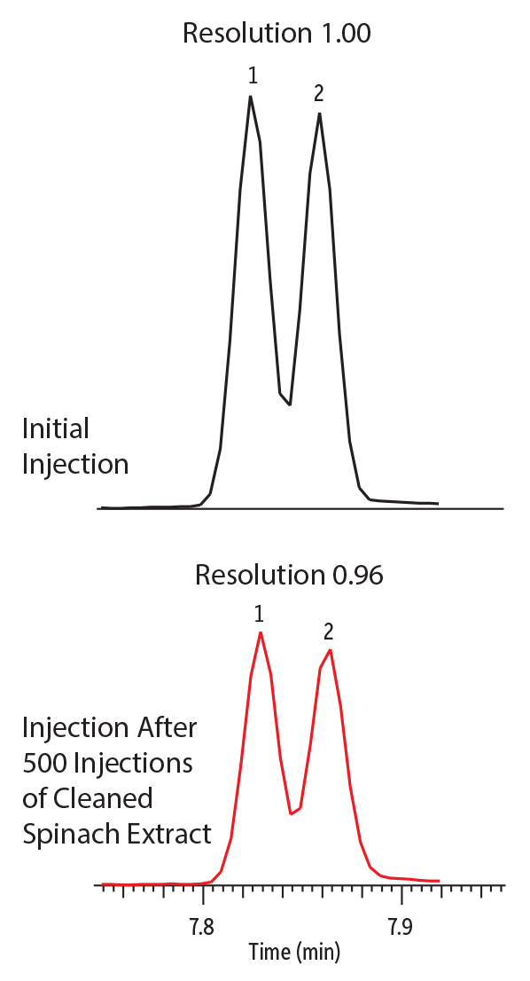
Implementing any new technique can be a risk, especially for a fast-paced lab with a constant supply of samples awaiting analysis. To make that risk pay off, it is essential to have confidence in the new method’s stability. Once a successful LPGC-MS method has been developed and the column kit has been installed, you need to know that it is going to perform reliably over the course of a long operational lifetime. An LPGC column kit will provide stable performance over the course of hundreds of injections, as is shown in Figure 5 below.
Figure 5: Even after 500 injections of spinach extract under LPGC-MS, the resolution, peak shapes, and retention times of these isomers remained nearly unchanged over the course of the lifetime study.
| Peaks | tR (min) | Conc. (ng/mL) | Parent Ion | Product Ion | Collision Energy | |
|---|---|---|---|---|---|---|
| 1. | cis-Permethrin | 7.82 | 90 | 183 | 153 | 12 |
| 2. | trans-Permethrin | 7.86 | 90 | 183 | 153 | 12 |
| Column | LPGC Rtx-5ms column kit, includes 15 m x 0.53 mm ID x 1.00 μm analytical column w/1 m x 0.53 mm ID integrated transfer line and 5 m x 0.18 mm ID Hydroguard restrictor factory connected via SilTite connector (cat.# 11800) (cat.# 11800) |
|---|---|
| Standard/Sample | QuEChERS performance standards kit (cat.# 31152) |
| Diluent: | Acetonitrile |
| Conc.: | 9 µg/mL |
| Injection | |
| Inj. Vol.: | 1 µL split (split ratio 100:1) |
| Liner: | Topaz 4.0 mm ID single taper inlet liner w/ wool (cat.# 23447) |
| Inj. Temp.: | 250 °C |
| Oven | |
| Oven Temp.: | 70 °C (hold 1 min) to 320 °C at 35 °C/min (hold 5 min) |
| Carrier Gas | He, constant flow |
| Flow Rate: | 2 mL/min |
| Detector | TSQ 8000 |
|---|---|
| Transfer Line Temp.: | 290 °C |
| Analyzer Type: | Quadrupole |
| Source Temp.: | 325 °C |
| Solvent Delay Time: | 2 min |
| Instrument | Thermo Scientific TSQ 8000 Triple Quadrupole GC-MS |
| Sample Preparation | The spinach matrix was prepared from 10 g of homogenized spinach extracted with QuEChERS EN salts (cat.# 25849) and cleaned up with dSPE containing magnesium sulfate, PSA, C18-EC, and GCB (cat.# 26219). The matrix extract was then spiked with 30 μL of each of the QuEChERS performance mixes for a final concentration of 9 ppm, and the internal standard triphenyl phosphate (TPP) was added at a final concentration of 10 ppm. |
| Notes | Between the first and last run, 500 injections of spinach extract spiked with internal standard (TTP) were made. |
Traditionally, one of the most vulnerable parts of an LPGC-MS solution that employs a restrictor column coupled to an analytical column is the column connection itself. The environment of a GC oven can be tough on column connections. Repeatedly cycling over a wide range of temperatures can cause inconsistent expansion and contraction between the different material components of the columns and the connectors. The buffeting of GC oven fans during oven cool-down periods can also place a significant stress on any column connector. A leak at a column connector can be catastrophic for a batch of samples, resulting in reruns and often even column replacement. Add the influence of the MS vacuum at the column connector under LPGC conditions and the stability of that connection becomes critical.
These challenges are why Restek offers its LPGC solution as a preassembled kit. We have exhaustively tested different column connection technologies over the years, and the low-thermal mass, zero-dead-volume, inert connector used in the low-pressure GC column kit is robust and will remain leak free even after extended use. Our specially trained manufacturing personnel use specifically designed tools to reliably make the connection for you, and each column is leak tested as part of its quality control evaluation before being placed into stock.
With no loss of peak shape or significant variability in response, Figure 5 offers indirect evidence that no leak was formed during the 500+ oven cycles performed during the lifetime study. Table II shows the mass spectrometer’s direct evaluation of how well the GC-MS/MS system was sealed throughout the experiment.
Table II: Mass spectrometer leak-check results over the course of a 500-injection lifetime study. The response of the tuning compound was consistent throughout the study, and the masses of ions related to the presence of a leak (e.g., m/z 18, 28, and 32 for water, nitrogen, and oxygen, respectively) were determined by the instrument to be at suitably low levels, indicating that the system remained leak free throughout the lifetime study.
| # of Oven Cycles between 70-320 °C | % Leak Relative to Tuning Compound | Order of Magnitude of Tuning Compound (m/z 69) Intensity (10x) | Tuning Compound (m/z 69) Signal Full Width at Half Max (m/z) |
| 0 | 5.03 % - Pass | 107 | 0.70 |
| 100 | 4.69 % - Pass | 107 | 0.71 |
| 200 | 4.08 % - Pass | 107 | 0.71 |
| 300 | 3.85 % - Pass | 107 | 0.71 |
| 400 | 3.40 % - Pass | 107 | 0.71 |
| 500 | 4.59 % - Pass | 107 | 0.72 |
Even though an LPGC column kit is expected to have a long lifetime, it will need occasional maintenance based on the number and types of samples you analyze as well as the degree of sample preparation performed. Just like a conventional GC-MS column, it may be necessary to trim some of the column if replacing inlet consumables (like liners and seals) is not enough to restore system performance. However, unlike conventional GC-MS columns, you will not trim the analytical column section of the LPGC column kit. You only need to trim the restrictor column, where residue from samples may have built up. Trimming 10-30 cm off of the inlet side of the restrictor column should reestablish performance, but we recommend that you trim as little as necessary since the restrictor is only 5 meters long. Trimming more than a total of 3 meters may result in difficulty achieving and maintaining a stable head pressure in the GC inlet. If too much of the column’s length is removed, the restrictor may not isolate the inlet enough to stop the MS vacuum from affecting the GC inlet.
Note that retention times will change when the restrictor column is cut, so some method parameter changes will be needed. You can adjust the column length in the GC software setup conditions and work under the same flow rate. Or you can keep the same column length in the GC software setup conditions and manually adjust the flow rate to decrease the linear velocity. In both cases, this should account for the shorter length that results from trimming the restrictor column. If done correctly, there should be no need to change the MRM integration windows, but this should always be confirmed prior to sample analysis.
When it comes time to replace your LPGC column kit, we recommend that you replace the entire kit rather than attempt to disassemble it and make new column connections. The proven leak-free connection you get with a factory-coupled kit provides the easiest, quickest, and most reliable way of implementing LPGC-MS and benefiting from its faster analysis times and reduced helium consumption.
When a new LPGC column kit is installed, you will likely observe some shift in absolute retention times for your target analytes. This shift could be in excess of ±10 seconds. The relative separation between compounds should remain consistent from kit to kit, but the shift in absolute retention time may require you to reassign retention time windows to your target analytes. By performing a simple analysis using a standard in solvent where wide ion monitoring windows are used to make sure you catch the target analytes, you can quickly reestablish retention time windows, if necessary. You can also choose to change the carrier gas flow to match the preferred retention time.
Welcome to a Simple, Reliable Setup for Low-Pressure GC-MS
Taking advantage of your mass spectrometer’s vacuum system to greatly accelerate GC separations has never been easier. Restek’s low-pressure GC column kit for vacuum-outlet GC-MS makes increasing your instrument’s productivity as easy as a quick column change and method update. With this simplified setup, you can start processing more samples per shift, save money by using less helium, have more time for other tasks, or even put off that next big capital investment in a new instrument to accommodate your workload.
References
- B. Gruber, F. David, and P. Sandra, Capillary gas chromatography-mass spectrometry: Current trends and perspectives, Trends Anal. Chem. 124 (2020) 115475. https://doi.org/10.1016/j.trac.2019.04.007
- S.J. Lehotay, J. de Zeeuw, Y. Sapozhnikova, N. Michlig, J. Rousova Hepner, J.D. Konschnik, There is no time to waste: Low-pressure gas chromatography–mass spectrometry is a proven solution for fast, sensitive, and robust GC–MS analysis, LCGC North Am. 38 (8) (2020) 457–466. https://www.chromatographyonline.com/view/there-is-no-time-to-waste-low-pressure-gas-chromatography-mass-spectrometry-is-a-proven-solution
- S.J. Lehotay, N. Michlig, and A.R. Lightfield, Assessment of test portion sizes after sample comminution with liquid nitrogen in an improved high-throughput method for analysis of pesticide residues in fruits and vegetables, J. Agric. Food Chem. 68 (2020) 1468–1479. https://pubs.acs.org/doi/10.1021/acs.jafc.9b07685
- L. Han, S.J. Lehotay, and Y. Sapozhnikova, Use of an efficient measurement uncertainty approach to compare room temperature and cryogenic sample processing in the analysis of chemical contaminants in foods, J. Agric. Food Chem. 66 (2018) 4986–4996. https://pubs.acs.org/doi/10.1021/acs.jafc.7b04359
- S.J. Lehotay and Y. Chen, Hits and misses in research trends to monitor contaminants in foods, Anal. Bioanal. Chem. 410 (22) (2018) 5331–5351. https://pubs.acs.org/doi/10.1021/acs.jafc.7b04359
- S.J. Lehotay, L. Han, and Y. Sapozhnikova, Use of a quality control approach to assess measurement uncertainty in the comparison of sample processing techniques in the analysis of pesticide residues in fruits and vegetables, Anal. Bioanal. Chem. 410 (22) (2018) 5465–5479. https://pubs.acs.org/doi/abs/10.1021/acs.jafc.7b04359
- Y. Sapozhnikova, High-throughput analytical method for 265 pesticides and environmental contaminants in meats and poultry by fast low pressure gas chromatography and ultrahigh-performance liquid chromatography tandem mass spectrometry, J. Chromatogr. A 1572 (2018) 203–211. https://doi.org/10.1016/j.chroma.2018.08.025
- J. Hinshaw, Fast gas chromatography, LCGC North Am. 35 (11) (2017) 810–815. https://www.chromatographyonline.com/view/fast-gas-chromatography-1
- L. Han, Y. Sapozhnikova, and S.J. Lehotay, Method validation for 243 pesticides and environmental contaminants in meats and poultry by tandem mass spectrometry coupled to low-pressure gas chromatography and ultrahigh-performance liquid chromatography, Food Control 66 (2016) 270–282. https://doi.org/10.1016/j.foodcont.2016.02.019
- S.J. Lehotay, L. Han, and Y. Sapozhnikova, Automated mini-column solid-phase extraction cleanup for high-throughput analysis of chemical contaminants in foods by low-pressure gas chromatography—tandem mass spectrometry, Chromatographia 79 (2016) 1113–1130. https://link.springer.com/article/10.1007/s10337-016-3116-y
- J. de Zeeuw, S. Reese, J. Cochran, S. Grossman, T. Kane, and C. English, Simplifying the setup for vacuum-outlet GC: Using a restriction inside the injection port, J. Sep. Sci. 32 (11) (2009) 1849–1857. https://doi.org/10.1002/jssc.200900009
- K. Maštovska and S.J. Lehotay, Practical approaches to fast gas chromatography–mass spectrometry, J.Chromatogr. A 1000 (1-2) (2003) 153–180. https://doi.org/10.1016/S0021-9673(03)00448-5
- M.S. Klee and L.M. Blumberg, Theoretical and practical aspects of fast gas chromatography and method translation, J. Chromatogr. Sci. 40 (5) (2002) 234–247. https://doi.org/10.1093/chromsci/40.5.234
- K. Maštovska, S.J. Lehotay, and J. Hajšlova, Optimization and evaluation of low-pressure gas chromatography–mass spectrometry for the fast analysis of multiple pesticide residues in a food commodity, J. Chromatogr. A 926 (2) (2001) 291–308. https://doi.org/10.1016/S0021-9673(01)01054-8
- J. de Zeeuw, J. Peene, H.-G. Janssen, X. Lou, A Simple way to speed up separations by GC-MS using short 0.53 mm columns and vacuum outlet conditions, J. High Res. Chromatogr. 23 (12) (2000) 677–680. https://doi.org/10.1002/1521-4168(20001201)23:12<677::AID-JHRC677>3.0.CO;2-L